

Surface Detail: a modern DIY Analog Chorus
with Tap Tempo & Waveform Selection

Click image for high-resolution version
This is a fun little analog chorus/vibrato unit that has lo-fi capabilities that I quite enjoy. The design came out of two things.
The first: cleaning out my scrap prototypes drawer and finding a first draft of an analog chorus idea I’d briefly tinkered with and then promptly forgot in very early 2020 as I began designing the T-60.
The second: The selection of of the shelf BBD-based DIY projects out there are all pretty… antiquated. Some of the best designs are classic of course, but it seemed odd to me that no one had bothered trying to outfit something like a Small Clone with an off-the-shelf, pre-programmed digital LFO chip like the Electric Druid TapLFO or StompLFO. Well, I wasn’t really into just slapping two pre-existing things together, so instead, you get this.
One quirk I ended up not being able to utilize in the T-60 (due to that pedal’s regen capabilities) that I found a home for here was the ability to tap into the really gritty sound that a 571 compressor stage puts out. Yes, it’s pretty noisy, but it has a great lo-fi quality too. I wanted this to be optional, so I decided I’d allow the user to select between compressed and uncompressed versions of both the wet and the dry signal. Further, by using an on-off-on switch for the dry, you get a “dry kill” mode as well.
This design also leaves plenty of room for experimentation, which I highly encourage. I think this should give you a good starting point for BBD modulation.
As for the name, it’s in homage to one of the books in the Culture series of sci-fi novels by Iain M. Banks (ship names from this series are plastered all over the T-60 PCB as well, so it fits).
Note #1: Before we get started, I’m going to state outright that as I walk you through this, I’ll assume you either have a fairly sturdy grasp on the basics. I won’t explain every little thing, but I’ll do my best to include google-able terms for all the different parts of the circuit and provide links for further reading in places I think it may help.
Note #2: One of my own design quirks you may notice is that I try not to use many different component values. I can almost always, through calculation or trial and error, determine a way to use very standard values for pretty much everything. I picked this habit up hand-populating SMT prototype layouts. Hell, I’ve been known to use series and parallel combinations of standard values to get non-standard ones (though I haven’t done so here). I call it BOM (Bill of Materials) golf.
Anyway, enough preamble. Here we go:
Input Section
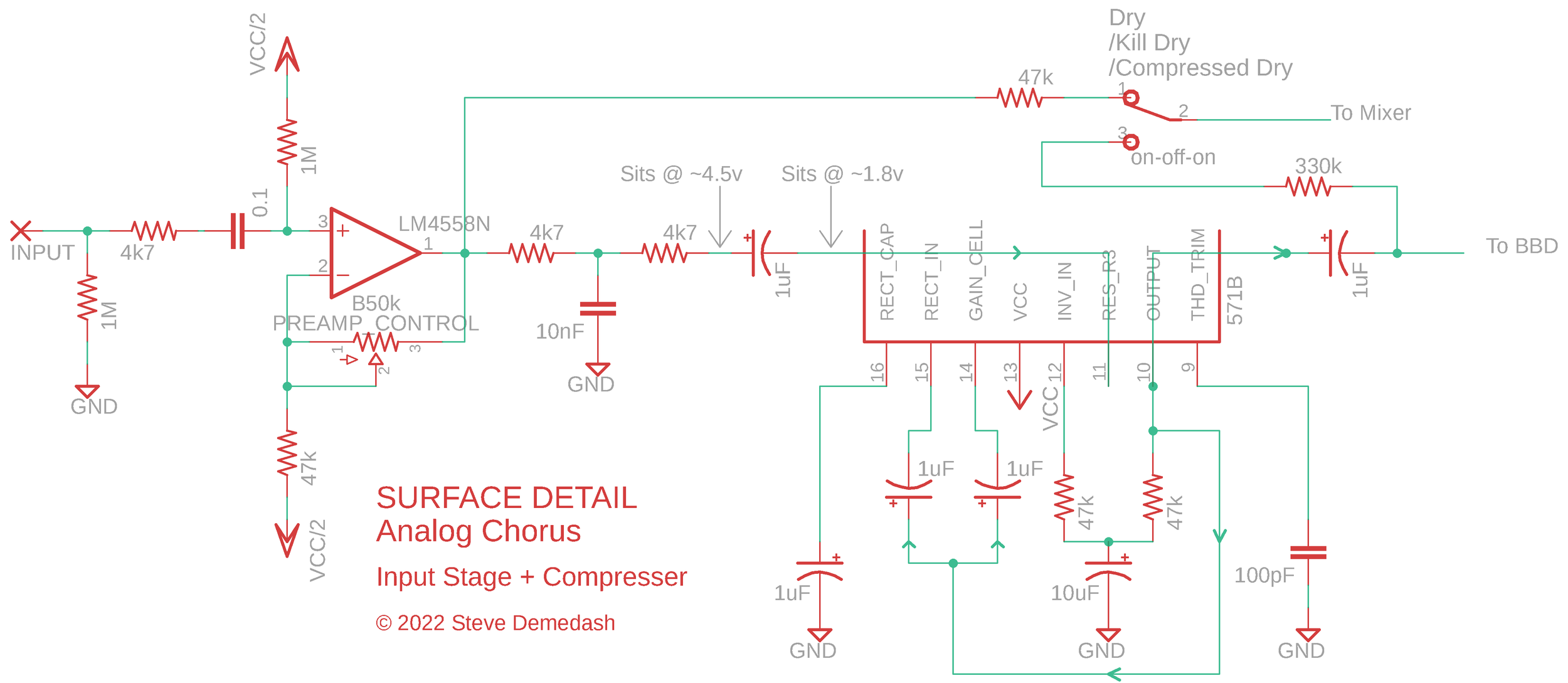
Yeah yeah I redrew it. Sometimes it helps to see things arranged differently. You’ll live.
The input is a pretty basic non-inverting op amp configuration. The Preamp control, set to minimum, will have this stage act as your standard non-inverting buffer with unity gain. At maximum, you end up with a gain of about 2.
Changing the amount of boost at the input changes the dynamics of the compression - how quickly the compression kicks in, and how hard it has to work to keep the signal even. If you’ve already got a hot input, you can probably get some clipping out of it - whether that is desirable to you is left in your hands.
The signal then splits into two paths - one to the switch, one to the next stage of the circuit.
The switch is a Single Pole, Double Throw type (of the on-off-on variety), and selects which version of the unaffected signal goes into the output mixer. Choosing the middle position, “kill dry”, stops any dry signal from passing, meaning that only the wet signal goes to the output mixer, and rather than chorus, you get vibrato. The other two options are (1) ‘dry’ as in, purely dry and unaffected by anything besides the preamp; (2) compressed dry, as in, the signal taken at the output of the compressor before it passes into the BBD. The resistors that sit between the two different signal sources and the switch are sized to account for the signal level coming out of that source. We’ll revisit this when we get to the mixer stage.
The other branch of the split signal goes through a one pole low pass filter (in this case, an anti-aliasing filter), rounding off some of the highs that can cause issues when the samples in the delay line start getting put back together at the output. As an interesting aside, I’ve found this pre-BBD filter to have a larger impact on noise reduction than the post-BBD filtering does.
Next, the signal feeds into a compressor built using one half of the v571 (or SA571, NE570/571, etc, etc) compander (compressor/expander) chip. This is a feedback compressor, literally meaning, the output is fed back and controls the gain level. In this configuration, a controllable gain cell sits in the feedback loop of an internal op amp, and when the output increases in magnitude, the gain cell’s output also increases, sending a larger signal to the inverting terminal, and as such, decreasing the op amp’s gain. When the output level decreases in magnitude, the gain cell passes less negative feedback through and the gain increases. With low/no input, the gain sits at maximum. Put another way, the compressor “tries” to keep the output level constant, raising the volume of quiet signals and reducing the gain of louder ones.
2. Delay Line & Tone Control

The compander chip above biases its signal at around 1.8v, whereas the BBD is biased to 4.5v, so we need to isolate these two bias voltages to prevent them from trying to equalize in the middle and pulling both stages away from their proper bias point. We do this using a ‘decoupling’ capacitor (not a specific type of capacitor - simply named that for its role here). Note that the positive side of the polarized capacitor should face the higher voltage bias point.
Regarding the 4.5v bias, we are lucky that the v3207 likes to sit at VCC/2, as it prevents us from needing a trimmer to properly set the bias. However, if you want to use a v3208 chip for wider pitch swing or a 3204 for a more shimmery sound, you’ll need to use a trimmer to bias the input rather than using VCC/2.
The 1024-stage BBD samples the incoming signal’s voltage level incredibly rapidly, and passes those samples along down a chain, taking one step every time a clock pulse comes in. There are two alternating chains inside, hence the two alternating clock pulses, and two outputs. The two outputs are summed together and passed through another anti-aliasing & reconstruction filter (smoothing out the discontinuities between the samples, “reconstructing” the original continuous signal, minus any pesky clock noise). The clock speed here is high enough that it stays outside of the range of human hearing (above 20kHz) and as such we don’t need to do terribly much filtering. Conversely, in analog delays, where you have clock speeds that dip down to 8kHz or lower, filtering must be much heavier. It is this, rather than anything to do with BBD technology itself, that leads to the characteristically “dark” sound of analog delays. But I digress.
Next comes the tone stage. Typically, this type of circuit will boost bass and suppress treble when the control is completely CCW, and suppress bass/boost treble when the control is fully CW. I finessed it here to keep bass at 0dB and suppress treble when turned down, as boosted bass just sounded gross. This implementation does have a slight resonant peak, hitting 5dB around 300 Hz, but it doesn’t sound muddy or fuzzy, so it’s good as-is. When turned up, bass is suppressed and treble is boosted by about 17 dB, with a corner frequency at around 2.7 kHz.
After the tone stage, the 4.5v bias is again blocked with a decoupling capacitor as the signal is passed over to the expander stage, which sits at 1.8v.
3. Expander

This stage uses the second half of the 571 Compander chip. Both sides are the same - the behaviour is dictated by how it is set up. In this case, the input signal is coupled directly to the gain cell, which is placed before the internal op amp (whereas in the compressor configuration, the output is coupled to the gain cell, which is placed in the feedback loop). The Expander’s gain varies with the size of the input signal - larger input, higher gain - reversing the compressor’s effect. This way, low-level background hiss and whine is muted when you aren’t playing.
The “Wet Mode” switch allows you to select which version of the signal goes to the output mixer - the unexpanded (compressed) version, or the expanded version. The expanded version will be cleaner, but the compressed version has a certain lo-fidelity character that I quite like.
4. Output Mixer

The Output Mixer is where the Dry and Wet signals are mixed back together and sent on their way to the output.
Sometimes there is a mix control, other the two signal levels are static in relation to one another. The name for this type of circuit is an inverting mixer, because the signals meet at the inverting terminal of the op amp, and thus the phase of the mix is flipped/inverted with respect to the original. Why use an inverting mixer over a non-inverting one? There are several very good reasons you can read about here.
The switches, as mentioned before, allow you to dictate which signals get mixed.
For Dry, we have:
normal,
none/silent/kill dry
compressed
For Wet, we can select between
normal (expanded wet signal)
compressed (unexpanded wet signal)
This configuration allows for a number of interesting combinations, and by using a switch with a middle ‘off’ position for dry, we allow for vibrato. If you don’t have a switch with a middle off position, you can use a standard on/on switch - you just won’t be able to kill off the dry signal entirely.
The resistors that come before the switches are selected so as to yield an even output level, no matter which signal source you’re tapping. The compressed signals are significantly louder than the uncompressed signals, so larger resistors are used. Aside from the 47k dry resistor (selected to match the 47k feedback resistor so as to give unity gain), these values were selected empirically. Feel free to experiment with them.
Op amps tend to have issues driving capacitive loads. The 1k resistor helps decouple the output of the op amp from all that follows. There are other techniques for doing this, but this is a simple method that works well here.
The DC bias of the mixer stage is isolated from the output of the circuit using a 1uF capacitor (though anything from 100nF to 2.2uF would be fine). A passive volume control allows you to adjust the output level. The taper of the volume control is Linear (‘B’), but you may find an Logarithmic (‘A’) taper more appealing. All potentiometers in this circuit are 50k, but lowering this one to 10k won’t hurt at all. Lower output impedance is never a bad thing.
5. Digital LFO & BBD Clock

The modulation waveform is provided by the Electric Druid StompLFO. If you’d like to expand on the number of controllable parameters the digital LFO has, you could try using the more extensive TapLFO instead (use of the tapLFO will not be covered here, however).
The ‘FREQ’ input sets the LFO rate according to the voltage (between 0-5v) seen at that pin.
‘WAVE’ selects from one of 8 waveshapes spaced evenly through the 0-5v sweep (ie, around the sweep of the potentiometer).
‘DEPTH’ selects the size of the waveform output.
‘OFFSET’, unused (grounded) essentially sets a DC bias for the LFO output. It functions very much like the ‘Manual’ control on a flanger. It simply doesn’t impact the sound much (if at all) in this use case, and so it not worth putting on a knob. (I have some strong opinions about User Interface design, and one of them is that a parameter needs to earn its place on the control panel. If it doesn’t do much in your circuit, it shouldn’t be in the user’s face).
The LFO waveform is output via the ‘PWM’ pin on the StompLFO, and splits into two paths:
It goes through a 4.7k/10nF low pass filter on its way to the led that displays the modulation waveform’s level at any given point in time.
It passes through a 10k/100nF low pass filter on its way to modulated the BBD clock.
These filters smooth out the waveform and convert it from a series of digital on/off pulses to an analog signal that varies continuously from 0v to 5v. The LED doesn’t intrinsically require a filtered PWM signal to operate properly, but because indicator LEDs just aren’t always placed as close as possible to the rest of the digital circuitry, it’s best we filter the digital signal so that we don’t run the risk of the raw PWM signal inducing oscillations in the analog ground plane or in nearby analog signals.
The clock circuit here is fairly reminiscent of the Boss CE-2 clock circuit (you can read an in-depth analysis of the entire CE-2 circuit here). An oscillator circuit is built around a 2N3904 transistor - it continuously charges the 47pF capacitor, and then when it is full, the capacitor discharges and a clock pulse occurs. To modulate the clock, we vary the starting charge of the capacitor (the point at which it resets to after each discharge). The higher the starting value, the less time it takes to charge up, and the faster the clock pulses are output. A lower starting value means a longer time to charge up, and thus slower clock pulses.
The diode between the LFO and the Clock ensures that current only flows in one direction. A couple of adaptations were necessary to get this style of clock to work with an LFO that output values between 0v - 5v (rather than having a range in the center of the supply voltage, like a traditional analog LFO).
The issue is that whenever the output of the LFO goes below the forward voltage of the diode, the diode stops conducting. Thus, funny little flat dropouts are audible in the modulation waveform whenever the LFO stops being passed to the clock at the valley of each wavecycle. The remedy to this was to use a diode with a lower forward voltage than the traditional 1N4148 (0.5v). The second was to bias the anode of the diode such that this point of the circuit remains higher than the forward voltage drop of the diode even when the LFO outputs its lowest possible value. A 47k resistor was found to be the best option here, but feel free to try different values. Lower resistor values will mean more idle current gets passed to the oscillator and the clock will ‘rest’ at a higher frequency. Higher resistor values will result in a lower bias point and less idle current passing through the diode, resulting in a slower resting clock frequency. Too high and you’ll end up with the LFO dropout issue described above. The 100k bias resistor on the other side of the diode has a similar purpose.
The v3102 generates two clock pulses (inverted copies of one another) and passes them over to the v3207. It also generated Vgg, a special 3rd supply voltage that the 3207 needs. Vgg is about 14/15 * VCC. The 10uF Capacitor acts as a charge reservoir for Vgg, helping to keep it stable and steady.
6. Power Supply

Most of this is pretty straightforward. The Ferrite beads help dampen any high frequency noise that may come in through the supply, and keep the noisier BBD/digital ground isolated from the ground node used by the rest of the circuit.
The 1N5817 diode protects against reverse polarity.
Half of an op amp is used to buffer the voltage divider. The 47k/47k voltage divider gives us a reference voltage at half the supply voltage. The 47 uF Capacitor helps filter ripple and act as a charge reservoir. Buffering this with an op amp has several benefits. By using an op amp to buffer this level, we can isolate the divider from the loads that connect to it. The output impedance of the buffer is also very low, which reduces loading effects on the divider. In essence, a buffered helps prevent your circuit from pulling the reference away from half the supply voltage, and helps prevent signal bleed-through at the reference node.
The indicator LED is shown here - the footswitch will connect the two pads when the effect is active, grounding the cathode of the LED to light it.
The BBDs in this circuit will be damaged by voltages around/over 12v, so this circuit may be a candidate for an over-voltage protection scheme if you wish to include one, but that will be left as an exercise for the reader. The scheme I use in the T-60 relies on components that are only available in surface mount packages, to the best of my knowledge. A 47 ohm resistor after the 1N5817, followed by a 10v zener diode may be a decent solution for protection up to 18v, but I haven’t tested it in this situation and it may drop the supply voltage too much to be worthwhile.
Summary
This was a fun one to do. If there’s interest I may tinker a bit and get a companderless version up and running for a stripped-down version. It would lack the lo-fi aspect I really like about this one, but companders are a bit of a headache to source these days anyhow.
If you don’t feel like building this yourself, or just want to check out an amazing sounding digitally modulated analog chorus with an extensive control array and an incredibly wide tonal palate, check out the T-60 Analog Modulator!
Mod Ideas:
This design leaves a lot of room for experimentation! It will give you a good starting point to deviate from. Some potentially cool ones:
Add a vactrol to the dry signal path, and hook it up to the same LFO, to add in some tremolo
Use a rail-to-rail op amp to get an inverted copy of the LFO wave. Turn the dry path into a harmonic tremolo
Using an inverted copy of the LFO, use vactrols between the mixer and both switches to have the output signal alternate between wet and dry rhythmically
Use a second LFO (analog or digital) to do any of the above, giving access to polyrhythmic options
Build a voltage-controlled Low Pass Filter on the dry side using an LM13700 and run it at a slower rate than the vibrato using a second LFO. It might take some finessing but you could likely get a half decent Leslie Speaker effect this way.
Use a v3208 for wider pitch swing
Use an MN3204 for shorter latency and a more shimmery sound
Use a second LFO hooked up to the FREQ input of the StompLFO (though the LFO signal must not exceed 5v) for a rate-ramping effect.
Usage
Do what you like, just credit me if you do something with it that makes you money, and don’t be lame and sell ready-made versions of this as a commercial product.