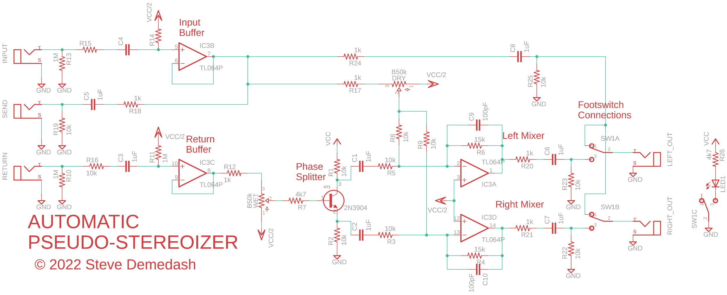
Automatic Pseudo-Stereoizer
Many Stereo Chorus units use an old phase-flipping trick to achieve a wonderful depth of field. The wet and dry are summed and output to the left channel, while the right channel is fed the sum of the dry signal and a flipped version of the wet signal.
In other words, Left = Dry + Wet, Right = Dry - Wet.
The depth of field is created by the interaction of the dry and wet signals as the wet “moves”. As such, higher modulation depths give the impression of a greater space.
Of course, this type of stereo chorus is not to be confused with Wet/Dry output, or with multi-voice choruses, such as the Boss DC-2, which use multiple separate wet paths. This type of chorus only has one wet path and one dry path.
This technique does come with pitfalls. What do you think happens if you collapse the stereo signal to mono?
Thats right, Mono = Dry + Wet + Dry - Wet = 2xDry. And just like that, poof! Your effect is gone. Sometimes your signal will be collapsed even without you asking for it to be. That’s right - even without your consent. Stereo I/O reverbs and Stereo I/O digital delays are notorious for this. They leave the inputs unsummed for their dry lines, but they collapse the inputs before processing the wet signal. Which means that your effect will still be present on the Un-reverberated portion of the output, but not on the reverberated part. If you mix your summed stereo effects fully wet, this will be an issue. If not, you may be fine with it. Otherwise, sometimes it’s just best to pick and choose which pedals get to do the stereo thing.
Important point: Stereo-ness is not necessarily cumulative - ie, going out of your way to use every stereo-capable effect you have in stereo mode is likely not the best way to get a nice stereo sound. You’ll end up with competing techniques and it will probably sound muddy.
Nonetheless, if you don’t have any self-important effects adding things together and ruining your good time late in your chain, and yet you still want a big wide depth of field, don’t you fear: here’s a handy little effect circuit that will let you turn [nearly] any modulation effect into a phase-inverted wide stereo effect. It will also make Brian Neunaber sad! Whether or not this is a desirable outcome is left as a choice for the reader.
Before we go any further, lets just all take a moment to appreciate that I haven’t actually built one of these yet, so the design is unverified and entirely theoretical. But it is based on circuits I have experience with, so I’m relatively confident I haven’t screwed anything up too badly. Anyway, let’s dive in!
Inputs, sends & returns
The input is passed through a buffer, and then the clean signal is sent to several places.
The ‘Send’ jack, which you connect to the input of the effect you want to stereo-ize
The Dry Level potentiometer, which, you guessed it, lets you set the level of the dry signal in the output
The bypass pins of the 3PDT stomp switch (yeah yeah it’s buffered bypass, grow up).
The ‘Send’ jack is set up much like the effect outputs. A 1kΩ resistor for a bit of resistive isolation from the other branches stemming from the input buffer; a 1uF coupling capacitor that blocks the DC bias from the buffer stage, and finally a 10kΩ pulldown resistor, which drains off any charge that might otherwise get stuck on the other side of the capacitor. This ensures the send jack is held at a 0v potential to facilitate happy cooperation with any effect input it will be connected to.
The ‘Return’ jack, much like the input jack, has a high-impedance non-inverting buffer stage, which helps isolate it from whatever sound source is in the FX loop. Unlike the input buffer, the output of this one does not branch. Instead, it leads directly to lug 3 of a potentiometer set up as a passive attenuator, which lets you adjust the level of the wet signal before that splits into 2 and gets mixed with the dry.
Notice that pin 1 of the pot is connected to VCC/2. This is done to save us the trouble of using a capacitor to isolate the DC bias from it, as we’d need to if pin 1 were connected to ground. It still works the same way, since nature doesn’t care what voltage level you refer to as “ground”. The nice thing about doing it this way is that we can use that bias all the way up to the transistor. Rather than separately biasing the transistor base, that VCC/2 level will get it working beautifully.
Phase inverter
The transistor is the heart of this little f*cker. It’s a simple 2N3904 NPN transistor that outputs two versions of the signal - one in phase with the input, and one out of phase with the input. Remember how I said the right channel gets an inverted copy of the wet signal? Well, here at Demedash Effects we like to subvert expectations in the most meaningless ways possible, so we’re giving the inverted version to the left side and the un-inverted to the right. Deal with it, mom.
Mixers
The two signals are coupled through 1uF capacitors, as the bias levels at the collector and emitter won’t be nice VCC/2 levels like the next stage operates at. Both wet and dry go through 10kΩ resistors. They meet at the inverting mixer, which uses a 15kΩ feedback resistor to give a slight bump to the output. This way, you can use the wet/dry knobs to level-match the output to bypass, and the extra bump will help compensate if the effect in the feedback loop puts out a signal a bit under unity gain. The 100pF feedback capacitors simply act as a short for very high frequencies, helping reduce possible noise.
After the mixer stages, the signals are coupled through 1uF capacitors that remove the DC bias, and 10k resistors pull the outputs to ground level.
Bypass Method
The purpose of using buffered bypass is to allow use of a 3PDT switch and to send the clean output to both left and right outputs when you’re not stereo-izing. As a designer, it’s kind of a dick move to mute one of the outputs when your pedal is put into bypass. Like, “oh hey were you using that second speaker? Aw that’s too bad. Guess you shouldn’t have turned my glorious pedal off, huh?” Don’t be that guy. Your customer bought both of his amps, let him use them.
While true bypass requires at least 2 switch poles per signal to fully bypass an effect, this method only requires one pole per signal - ie, to select whether the output jack connects to the buffer or to the effect out. Thus we have one pole left over to use for the LED indicator.
You could potentially pull off a true bypass variation of this using a 4PDT switch and the millenium bypass method to light the LED, but I will not be entertaining your nonsense today so that implementation will be left as an exercise for the demented reader.
There is another idea that may to occur to you that I’m going to nip in the bud right now: using the configuration shown here but tapping the input jack signal rather than the buffer’s output. This won’t get you the true bypass you so misguidedly crave. The reason for this is that you’d never actually remove the effect circuit from the chain - the input buffer would always be connected to the input jack, acting as a load on your signal, even in bypass. This is exactly what the Crybaby wah pedal does, and people do not like it at all. So, no, don’t do something that is famously pooh-poohed.
Use:
In the effects loop, you’ll want to use something that can be mixed fully wet. Otherwise, you’ll have dry signal coming back in through the return, and that’d sound pretty rotten as you’d end up subtracting dry from dry on the left hand side.
It’s the sound of movement in the wet signal, brushing up against the static dry signal that really creates depth here. So any mono effect that can mix fully wet and creates a sense of movement would be fun to experiment with. Modulated Reverb, Flanger, Phaser, Ring Modulation, Modulated Filters, Harmonic Tremolo (maybe), etc etc. This isn’t to say something like fuzz couldn’t be fun - but with a non-time based effect, you run into the phase cancellation issue due to the wet & dry signals not being spaced far enough apart to avoid destructive interference.
Mod ideas:
Preamp with a gain > 1 - gain adjustable, of course
Replace the 10k pulldown resistor on the send with a pot, to fine tune the output level going into the fx loop
Remove references to Steve Demedash, name it the “Spicy Mama” and make anywhere from $50-$60 + possible street cred selling it on the black market
Going Further
Rather than making a standalone box, you can use this style of circuit in one of your designs to give pseudo-stereo output without much modification - though you will want to tweak the values of the resistors around the output mixers to finesse the levels.
It’s worth noting that if you plan to use a TRS output jack on a pedal with this type of stereo splitting, you will need to add a second clean buffer, who’s output will connect to the ring of the TRS when in bypass, while the main buffer’s output connects to the tip. The reason for this may not be obvious at first glance. If you were to use the circuit as it is here with a TRS output jack rather than two separate jacks, you’d run into a funny problem if you tried using your pedal with a TS/mono cable. The place where a Ring connection would be on the mono cable is taken up by the sleeve connection, which is held at ground potential. And if you ground the ring connection, and the ring connection is directly tied to the tip connection, voila! No bypass signal.
Not that I’d know this from direct experience or anything.
Anyhow, ‘til next time,
Happy Stereo-izing!*
*unless you are Brian Neunaber, in which case, I’m sorry for any pain this has caused you.


